Here you can read a fragment of one of the “Design and construction of large diameter foundation bored piles” course units, that delves into the geotechnical considerations of bored piles design
Bored Piles Design- Geotechnical Considerations
Axial Load Design Criteria
Piles lengths and cross-sectional dimensions are chosen based on two criteria:
- Working loads on Piles should result in settlements less than the allowable limits and the differential settlements between adjacent piles shall not cause any damage to the super-structural elements.
- Pile working loads shall be safe enough not to cause failure in skin resistance or end bearing resistance.
Design and construction of large diameter foundation bored piles
Settlement Criteria
The first criterion arises from the kind of structure the piles are supporting. Settlements are calculated as shown in module 3 or by more sophisticated methods such as finite elements and checked with the allowable settlements. Many settlement criteria are given in literature, but it is the duty of the structural engineer to issue the requirements for the project. Definitions of settlement criteria is shown in Fig. 4.1.
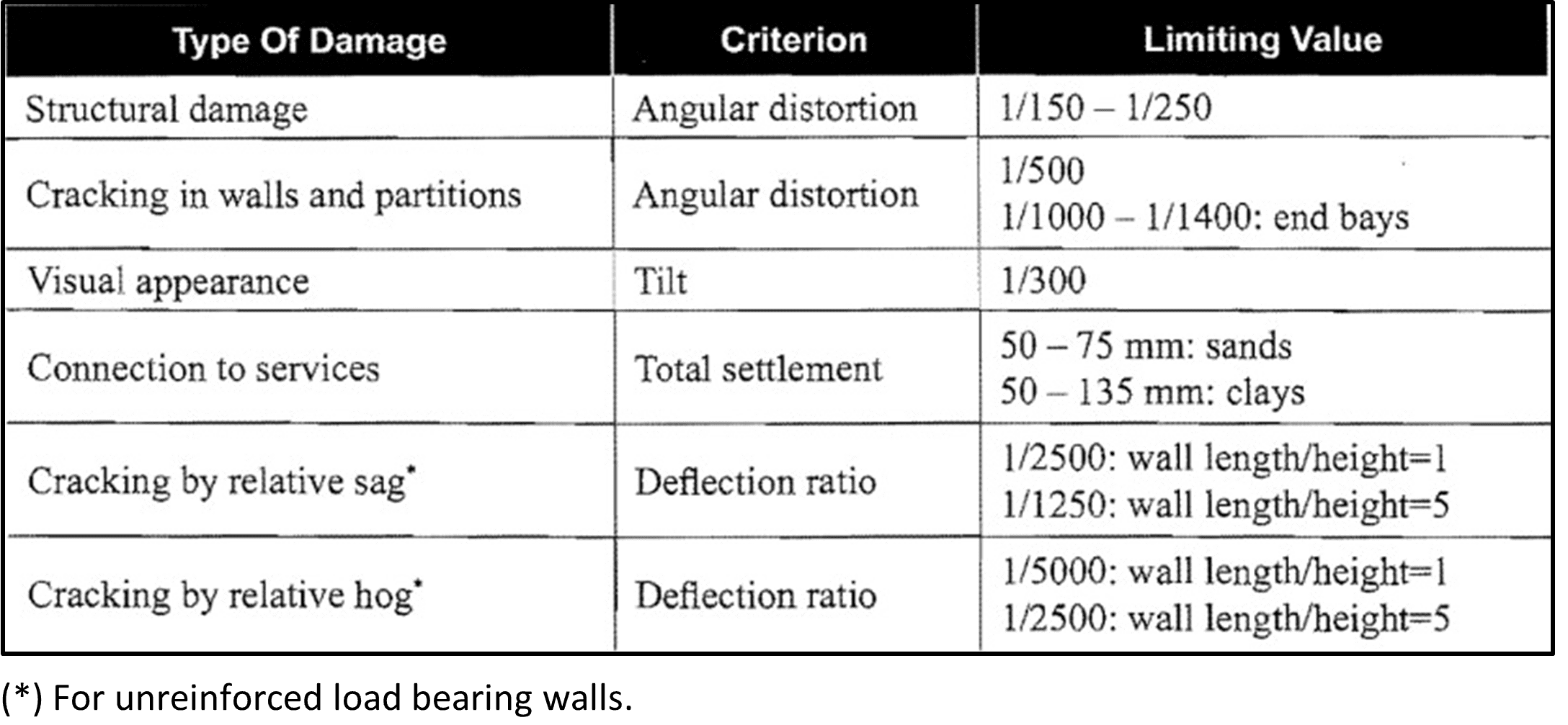
Some rules are given in Table 4.1 from CFEM (Ref.23).
The above criteria for settlement are used for comparing the structural settlements, hence, the pile groups and pile cap settlements.
The criteria for settlement of single piles is governed by the individual pile effect on the structure through its share in pile group behavior but in the same time the settlement of individual pile has its own criteria. In general, the shaft resistance is mobilized with very little movement, typically 5 mm to 10 mm or in percentage of pile diameter around 1% (ex: if you have a 1m diameter pile we expect the skin friction to be fully mobilized at around 10mm settlement), whereas the toe resistance when embedded in soil requires longer movements typically between 5 % and 10 % of the pile diameter. Hence, the actual load-settlement response of a single pile is a function of the relative contributions of shaft and toe resistance, the ground conditions, and the method of pile installation.
In many projects you may find the allowable limit on settlement of an individual pile during load tests to be around 10mm at working loads and to ensure elasticity the Engineer may ask for 1.5 times that settlement at 1.5 times the working load.
It should be kept in mind, that the net settlement is an important factor to check the recoverability of settlement and hence it is kept to a limit of 40% of the total settlement at the maximum proof test load and sometimes even less percentage at the working load level.
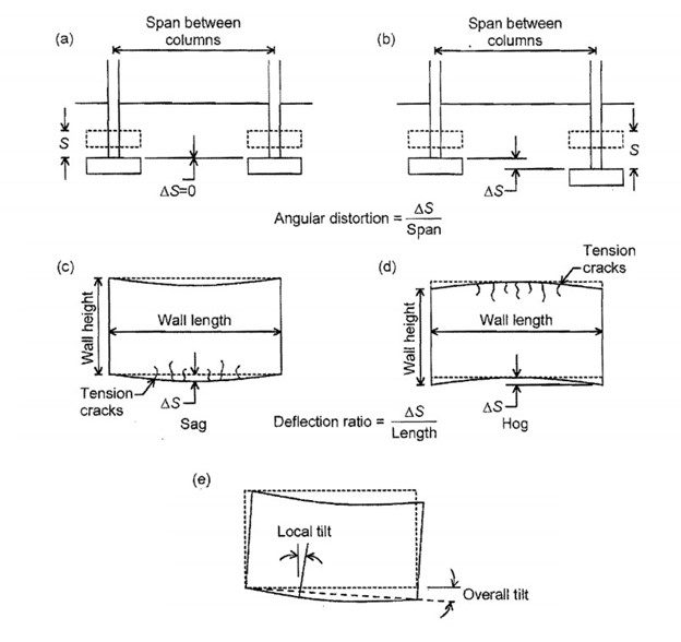
Table 4.1, Allowable settlements in structures
Factors of Safety
The allowable load on a pile may be determined using some safety factors applied on its carrying capacity. Using Qult and Tult as the total ultimate carrying capacity of the pile in compression and uplift (tension), with the components of Qbult and Qsult for end bearing resistance and ultimate skin resistance, four types of safety factors may be defined through the following equations for the allowable carrying capacity of the pile;
Qall= Qult/ FS1
Qall= Qsult /FS2
Qall= Qsult/ FS3 + Qbult/ FS4
While for the uplift only one factor of safety is there FS5:
Tall= Qsult/ FS5
In ACI 336 the factor of safety FS1 is called the global factor of safety and is usually taken as 2 to 3 with the most common value of 2.5. The lower side may be adopted when the design is validated by preliminary tests and it is increased as the uncertainty increases.
FS2 is also a global factor of safety but it is used when the pile is required to have minimal settlements where it controls the skin resistance only. As the skin resistance is kept within the elastic (recoverable range of settlement) FS2 is very useful to control the pile design. Usually, it is taken as 1.7 to 2.5 with a common use of 2.0. The value 2.0 keeps the skin friction at working loads less than half the ultimate value and settlement calculations can still be performed using elastic theories. A little difference from recoverability may occur at loads higher than the working load. The difference increases if the modulus of the soil is estimated higher than actual values.
FS3 and FS4 are called the mobilization factors of safety. They control how much of each component is participating in resistance. FS3 is taken from 1.0 to 2.0 while FS4 may be between 3.0 to 5.0, depending on installation method, layer conditions, method of obtaining the ultimate resistances and how confident is the designer in the design parameters.
If field test methods are adopted such as designing based on SPT N values, higher FS values are chosen. As much there is confidence in the design lesser factors of safety may be used.
FS5 is usually taken for uplift depending on skin resistance. The skin resistance for tension loads is usually taken as 2/3 to 0.75 of that foe compression. It means FS5 may be taken as 3 to 4. A value of 3.5 is widely used for uplift.
British standard BS8004:2015 asks to decrease the calculated skin resistance and end bearing if field tests are used (such as SPT), see Table 4.2, or if pile load tests are used to obtain the ultimate carrying capacity, see Table 4.3.
The minimum of the values obtained from minimum field estimates or the average field estimates shall be adopted. The same applies for values obtained from pile load tests.