Here you can read a fragment of one of the “Advanced Soil Mechanics” course units, that delves into the efective stress concept in soil mechanics
Effective stress
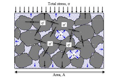
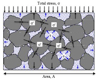
The loads applied to soil masses are carried by either the solid grains or the water in the pores, and at times by both. With reference to Figure 1.5, as the pore water is loaded (via the applied total stress, s) the pressure within it (u) increases causing the water to flow out of the soil, and the load is transferred to the solid grains (s‘). The flow of water under pressure out of a soil mass is called drainage. The rate of drainage depends on the permeability of the soil. Engineering behaviour involving strength and compressibility depend on the intensity of stresses passing through the solid granular fabric of the soil, i.e. effective stresses.
Ground movements and instabilities can be caused by changes in total stress; e.g. loading due to foundations, unloading due to excavations. They can also be caused by changes in pore pressures; e.g. slope failures which occur after rainfall due to increasing pore pressures. In fact it is the combined effect of total stress and pore pressure that controls soil behaviours such as shear strength, compression and distortion.
This combined effect is called the effective stress (s‘) and is given by: Effective stress = Total stress – Pore water pressure
Terzaghi’s principle of effective stress
Karl Terzaghi was born in Vienna and subsequently became professor of soil mechanics in the USA. In 1936 he was the first person to propose the relationship for effective stress. All measurable effects of a change of stress, such as compression, distortion and a change of shearing resistance, are due exclusively to changes in effective stress.
The adjective effective is particularly apt, because it is effective stress that is effective in causing important changes: changes in strength, changes in volume and changes in shape.
Drained and undrained soil
Throughout the rest of your career in civil engineering you will hear the expressions drained and undrained in reference to the state of soil or of loading conditions.
Drained does not mean the soil is dry of water. Similarly, undrained does not mean that every pore is full of water.
Refer again to Figure 1.5. As the normal stress is applied due to the external load, the pore pressure increases and this internal water pressure (known as the excess pore water pressure) causes the flow of water out of the voids. As the slightly pressurised water flows, the remaining water begins to experience a reduction in the excess pore water pressure. Eventually the pore water pressure returns to its initial value (i.e. the excess pore water pressure is zero). The rate at which this water flow occurs varies depending on the type of soil. Granular soils (e.g. sands) have much higher permeability than cohesive soils (e.g. clays) so the water drains much more quickly in granular soils.
When the excess pore water pressure equals zero the soil is said to be drained. Until that point the soil is undrained.
It should be fairly obvious that granular soils can become drained very quickly. They are said to be in a drained state. Consequently, when doing geotechnical analysis and design for granular soils, we will almost always do a drained analysis, or consider drained conditions.
Clays however have significantly lower permeabilities than granular soils and so drainage in clay takes much longer (years, as opposed to minutes/hours). Because of this, clays remain in an undrained state for a long time, as the excess pore water pressure very slowly dissipates and heads towards zero. When doing geotechnical analysis and design for cohesive soils therefore, we will consider undrained conditions and will do an undrained analysis. We will carry out a drained analysis too since the soil will after all eventually reach a drained state.
In undrained analyses, we consider the effect of the total stresses whereas in drained analyses we work with effective stresses. Thus, you will often hear the terms total stress analysis and effective stress analysis used to describe undrained and drained analyses respectively.
Now that we have seen how stresses exist in the ground, let’s look at what happens to those stresses when a load is now applied to the surface of the soil. We need to know what happens in order to (a) establish if the soil will be able to support the applied loading (a bearing pressure problem) and (b) to establish the amount of compression that the soil is likely to experience through time (a settlement problem).
Stress-strain relationship
From earlier years of study, we have seen that, for a material like mild steel, the stress/strain relationship is as shown in Figure 1.6 (a).
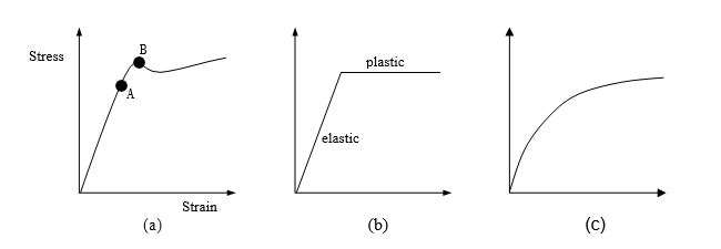
In Figure 1.6 (a) the straight-line portion of the plot indicates the extent of the elastic region (i.e. that range of stress over which the material behaves elastically) and point A is known as the elastic limit. Point B is known as the yield point and indicates the start of the plastic region.
For mild steel we can idealise the relationship to identify a definite elastic region and a definite plastic region as shown in Figure 1.6 (b). For soils however, there is no definite yield point and hence no definite elastic region and no definite plastic region as shown in Figure 1.6 (c)
However, we find that in most soils work, the induced stresses are either low enough to be well below the yield stress of the soil and it can be assumed that the soil will behave elastically (e.g. immediate settlement problems) or they are high enough for the soil to fail by plastic yield (e.g. bearing capacity problems).
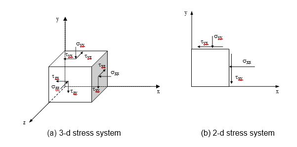
Stresses within a soil mass
When a soil is in a state of stress, following for example the application of a load, a 3-dimensional element of the soil will have 9 stress components acting on it: 3 normal stresses and 6 shear stresses (Figure 1.7 (a)). However, many geotechnical structures operate in a state of plane strain: i.e. one dimension of the structure is large enough for end effects to be ignored and the problem then is regarded as one of 2-dimensions, as shown in Figure 1.7 (b).